Closed Loop Vertically
Drilled Boreholes
Where limited soils resources make a horizontal trench loop infeasible, ground source heat pumps can be connected to an HDPE loop pipe within 6" diameter drilled boreholes.
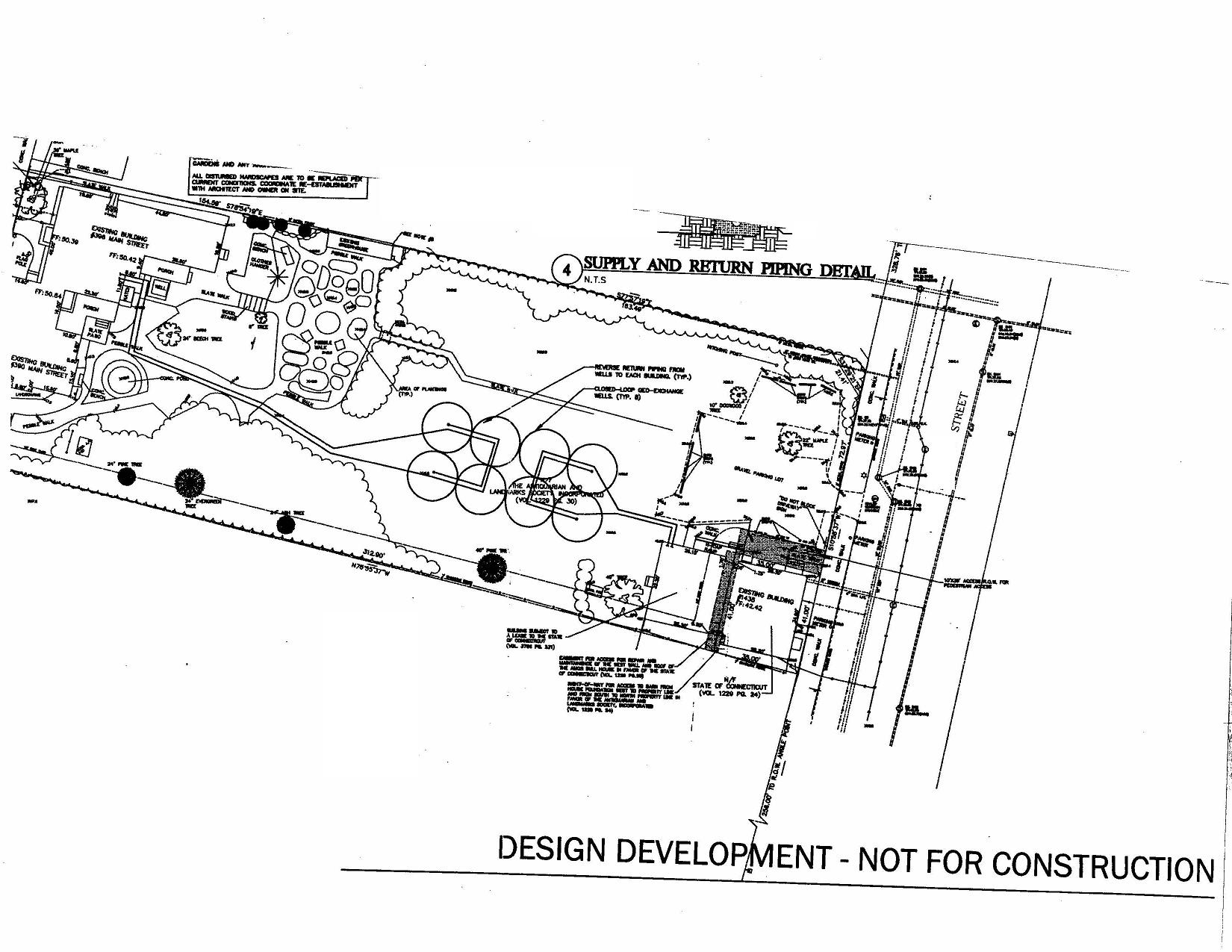
The preliminary plan below is for a proposed project where the client paid Peter Tavino PE for geothermal consulting work in separate authorizations. Note the eight well type boreholes with 20' separation radii, serving two separate buildings.
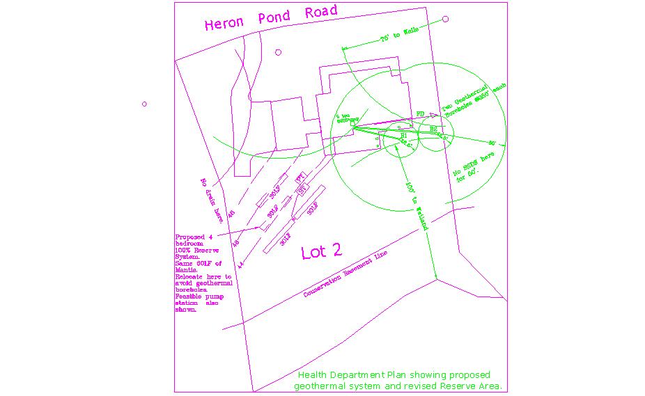
Here is a typical new home with two proposed boreholes.
A slinky trench alternative down gradient of the septic system and near the wetlands was less preferred than this design sealed by PJTavino.
When these bore holes are drilled, they will be thermally grouted, similar to the procedure shown in the picture gallery below.

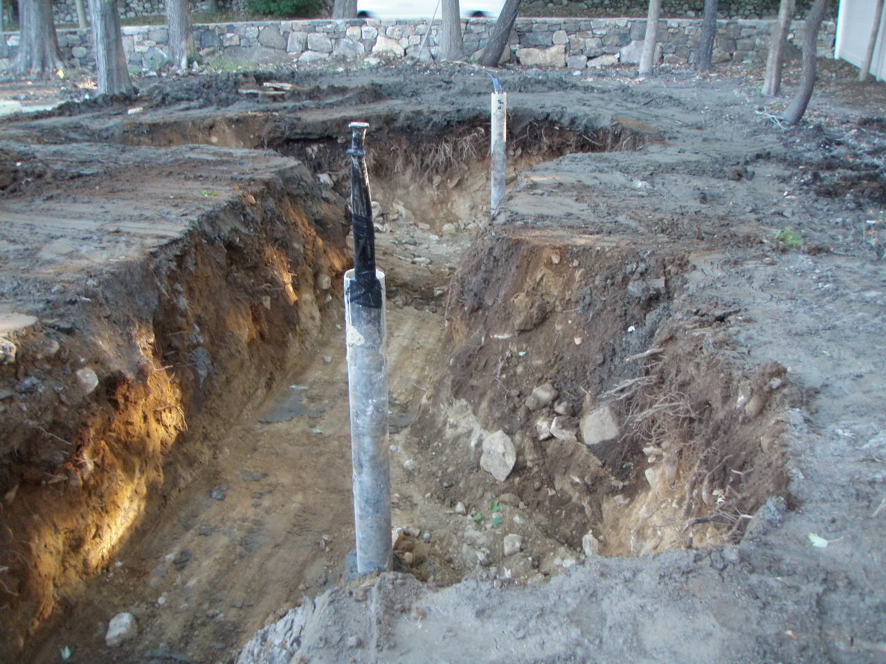
This is one of a pair of 350' deep identical bore holes drilled by Wragg Brothers to serve an historic Fairfield County home with planned addition.
Thanks to Tyler at Wragg Brothers in Roxbury, CT (800) 303-3097 for arranging the site visit to observe this job well done.
This ground exchanger will connect to a water to water GSHP with hydronic heat in the floor of the addition and to a water to air GSHP in the existing house.
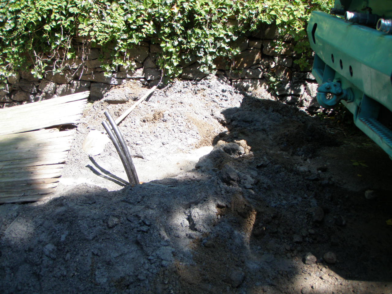
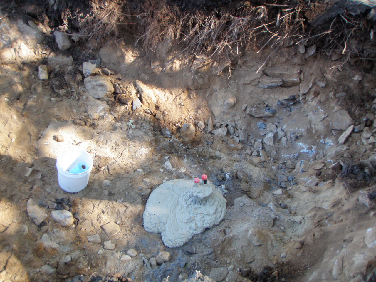
Note the 6" casing and clamps to hold the 1 1/4" loop pipe in place. This pipe is filled with water to resist buoyancy and plugged at the top ends to keep it clean..
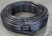
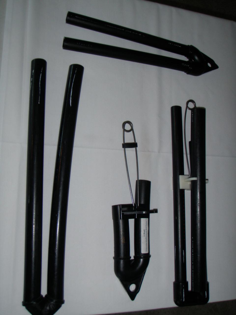
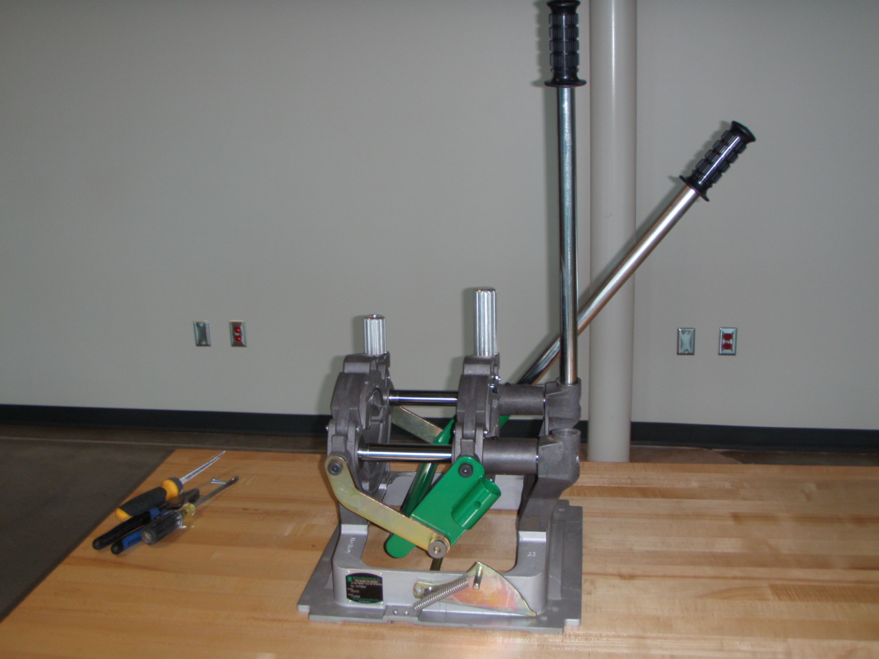
The 350' +350' = 700' of loop pipe arrives on the job with a U bend similar to the ones shown below for the bottom of the Bore Hole.
Here are the 350' deep loop tails exposed after installation to the bottom:
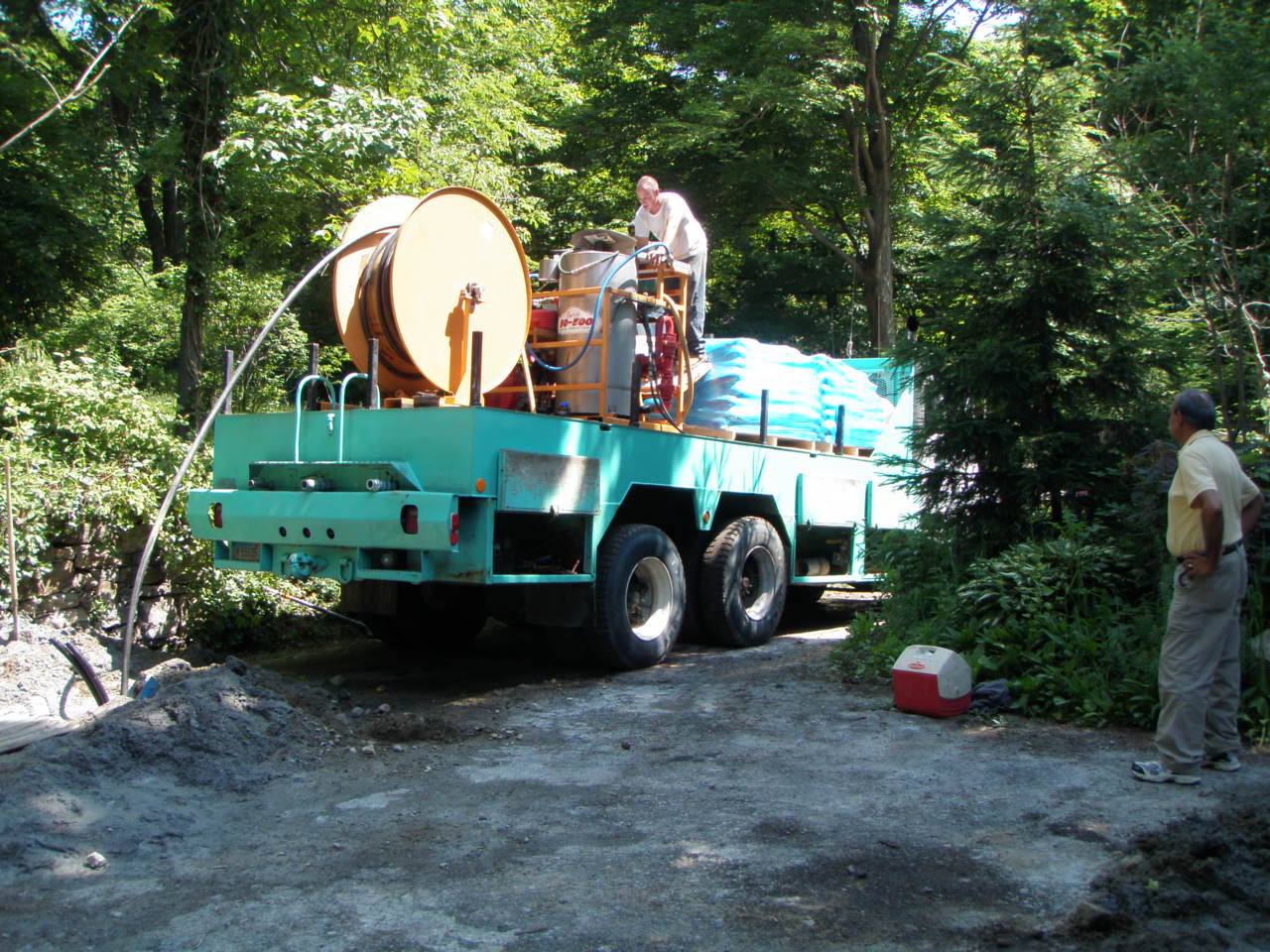
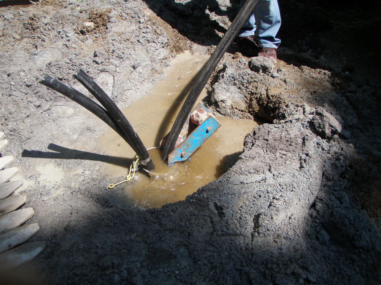
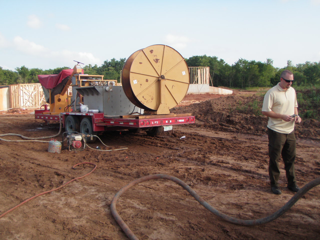
The grout truck is positioned to fill this borehole. Even though there are two holes, this is not an open loop ground exchange (pump and dump)
CT Clean Energy Fund discourages pumping groundwater through a GSHP, and will not rebate for it. Both holes will be closed loop grout sealed.
If grout is not used, or is placed improperly, a void could exist in the ungrouted portion deep below.
Good thermal heat transfer depends on proper bentonite and silica grout filling the entire 300' to 400' deep hole.

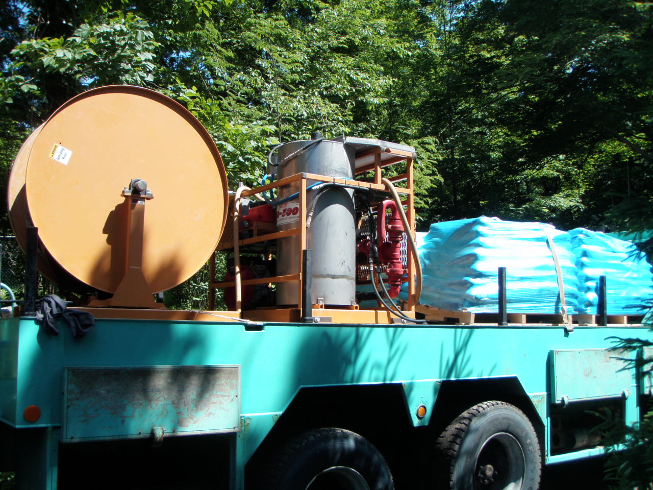
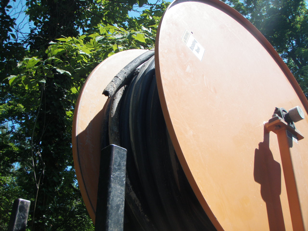
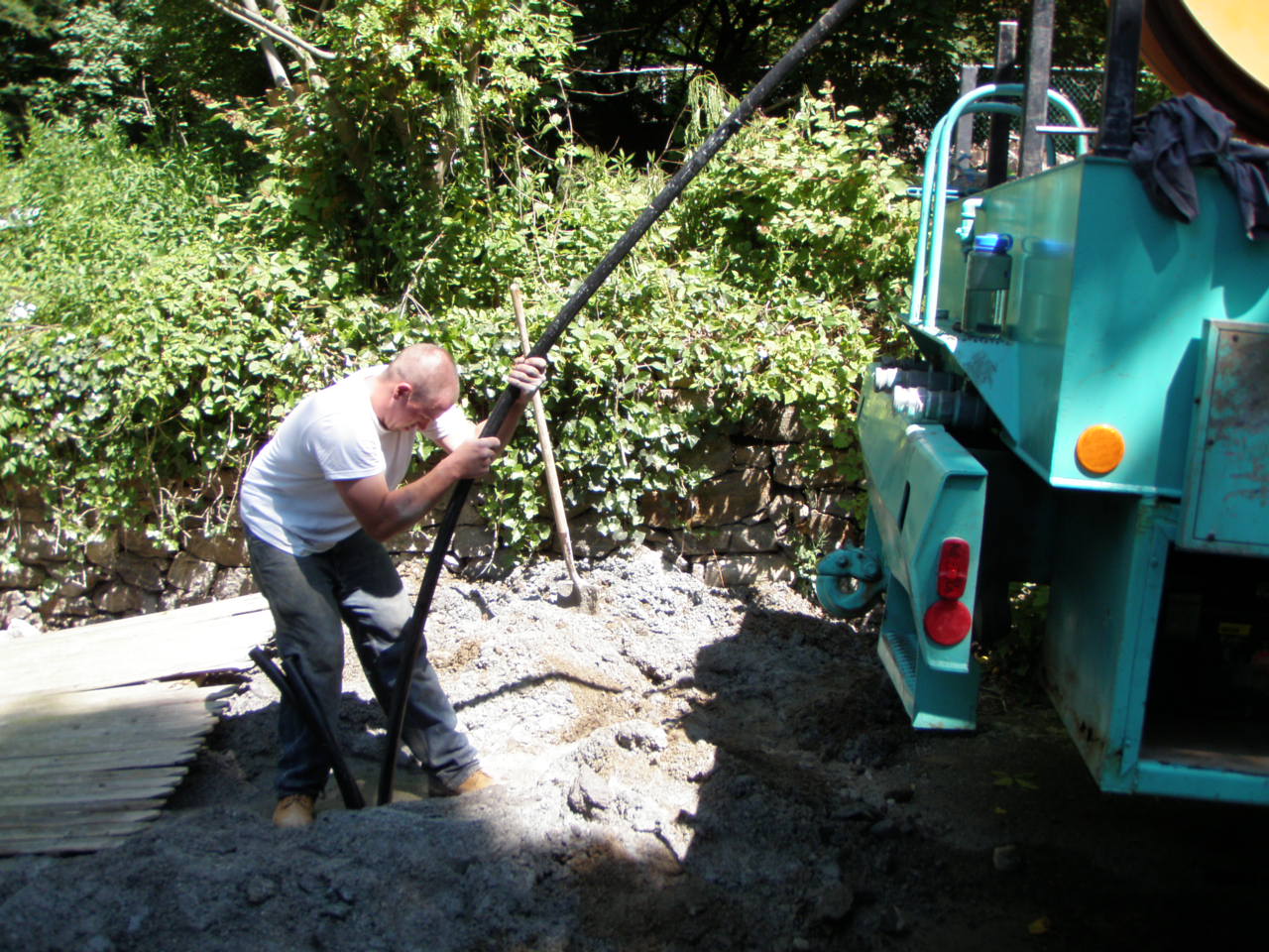
The tremie pipe is on a spool at the back of the truck. It is connected to the mixer nearby the supply of bagged silica sand and grout.
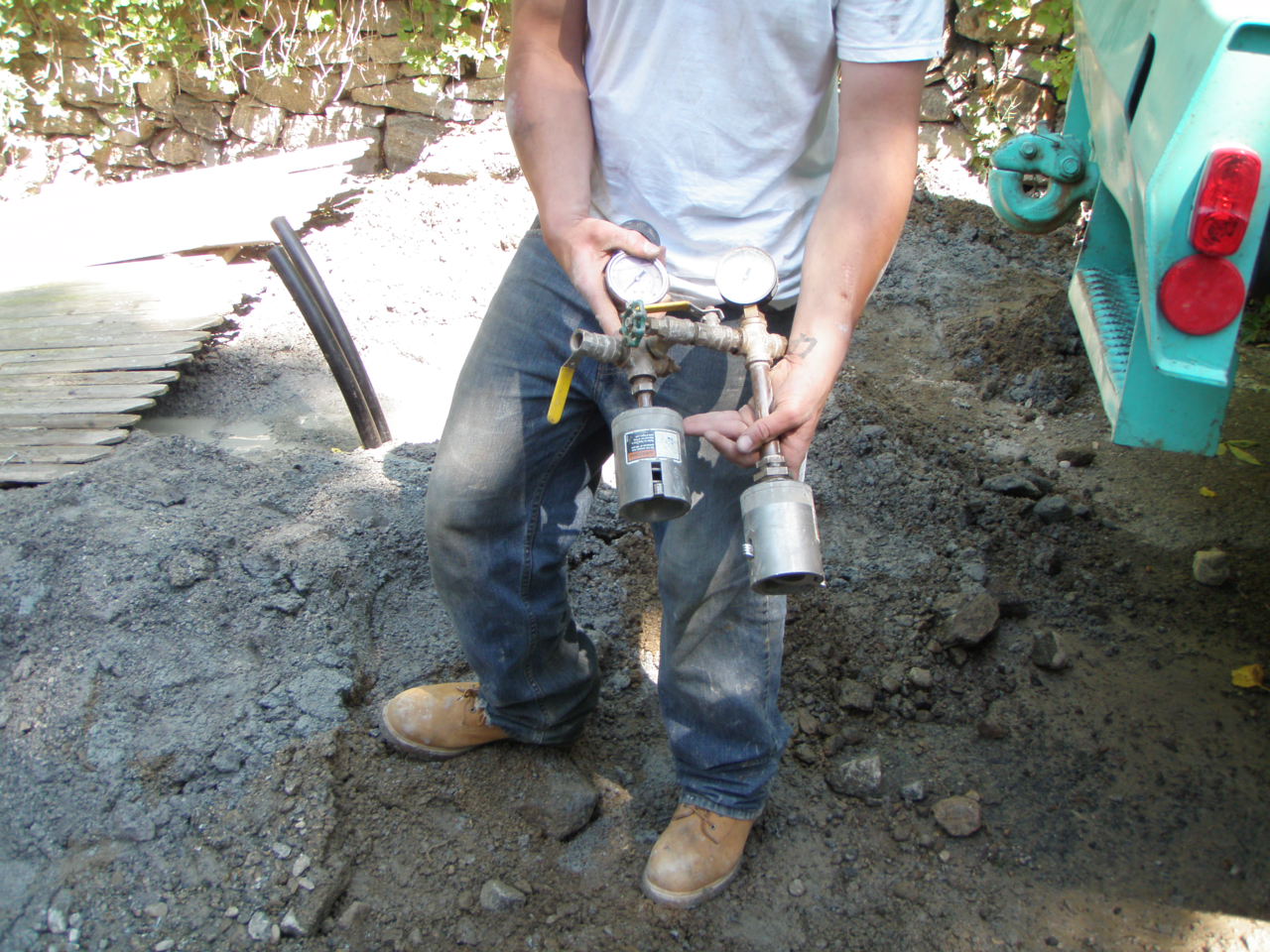
The grout installer checks loop pressure.
The tremie pipe is 1 1/2" HDPE, which is lowered to the bottom of the 350' deep borehole.
Air is allowed to escape from the other end so it does not resist insertion down the hole.
These twin rollers attached to the casing make insertion easier.
The 400' length of tremie pipe leaves 50' on the spool.
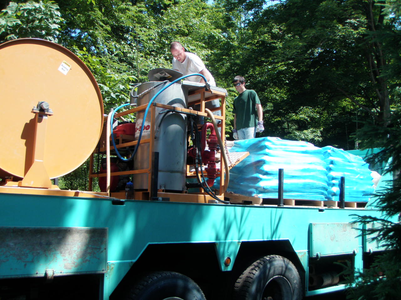
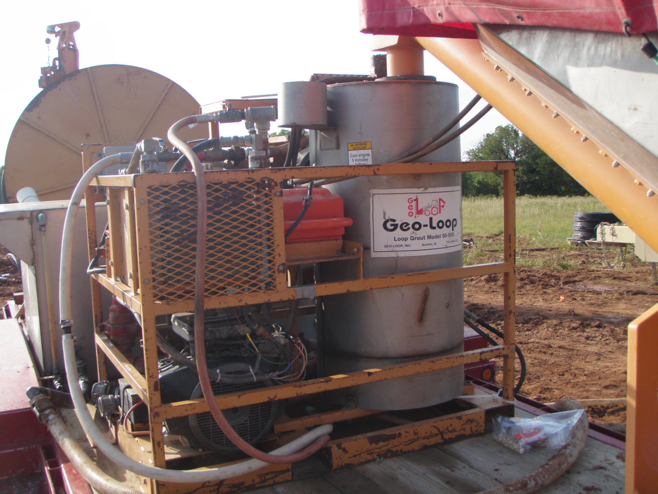
Grout is ready to be mixed and pumped into borehole.
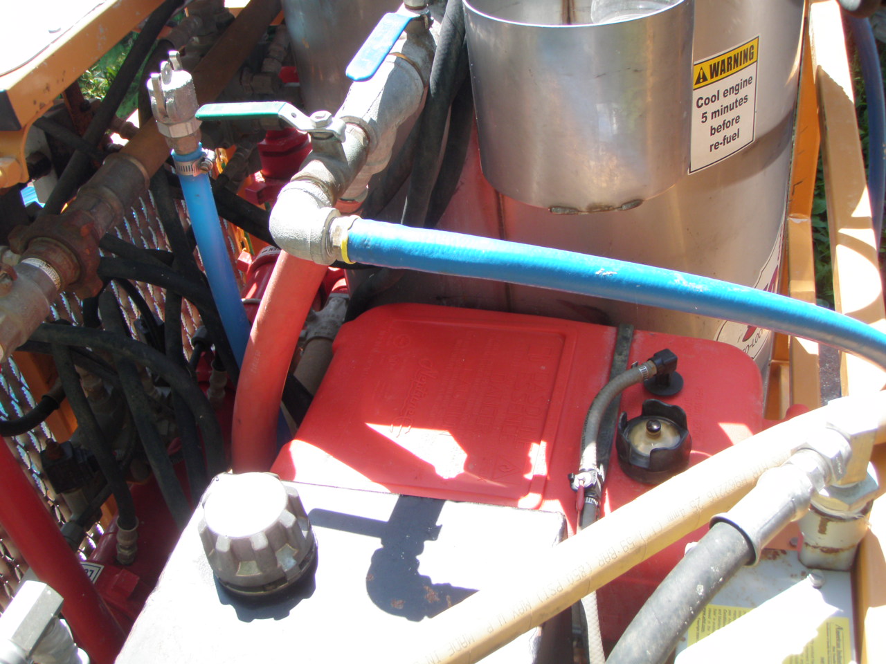
Water enters the mixing hopper as controlled by the valve.
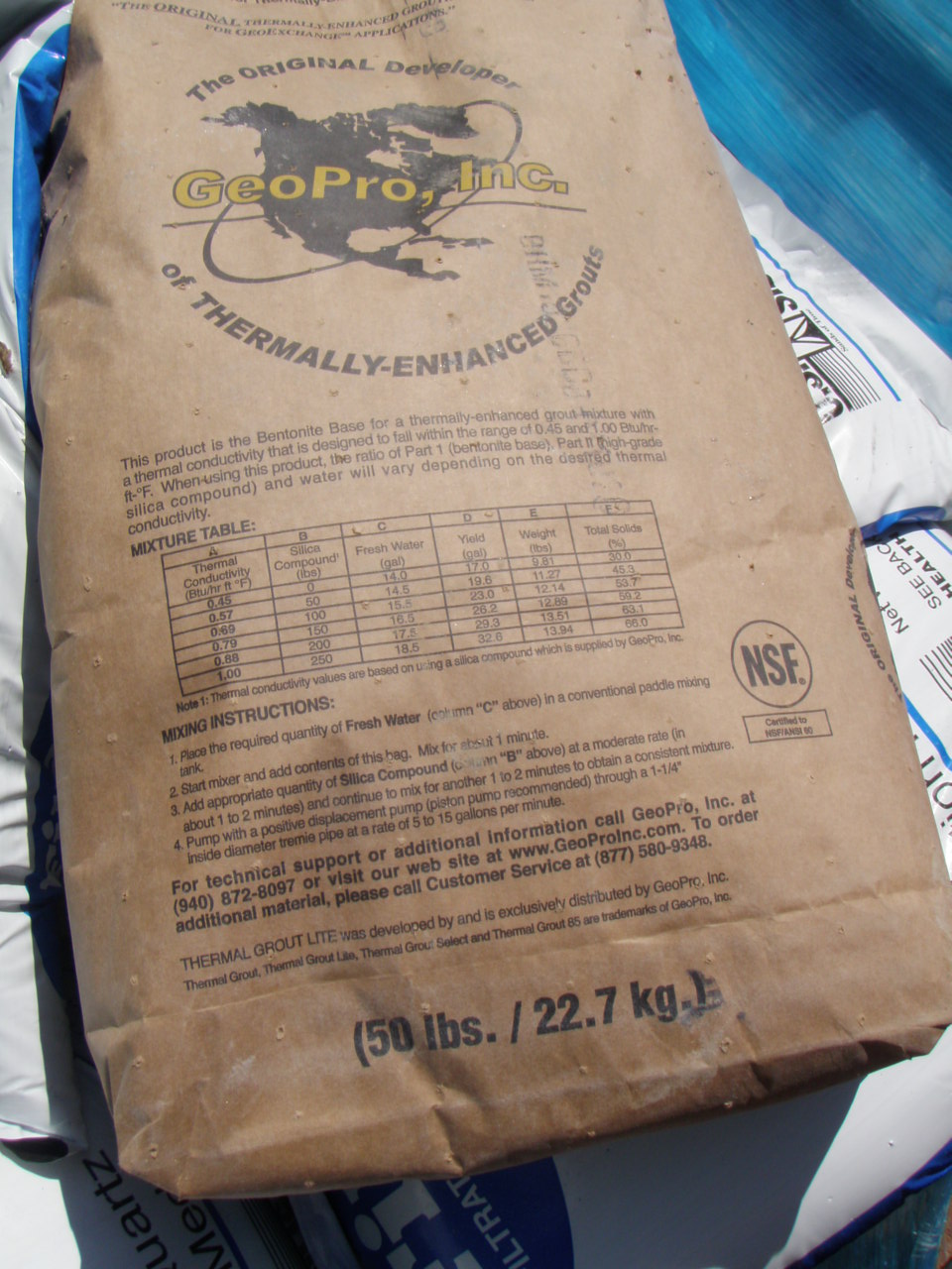
Bentonite Grout Thermal Conductivity will be 1.00 BTU/hr ft degree F. in the 1.4 rock.
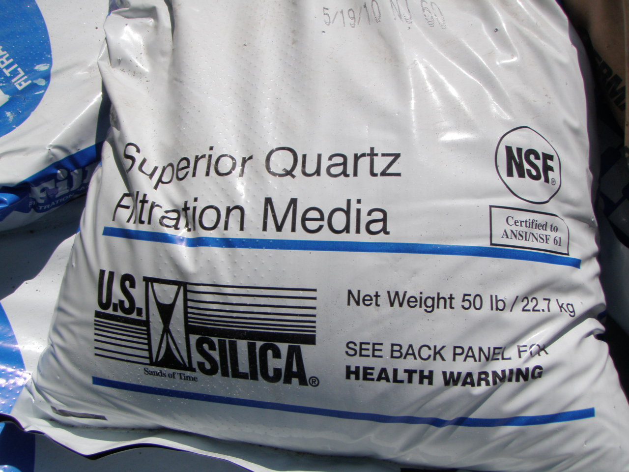
Five bags of silica sand are added for each bag of bentonite grout. This fills about 23'.
So the bore hole uses 15 bags of bentonite grout and 75 bags of silica.
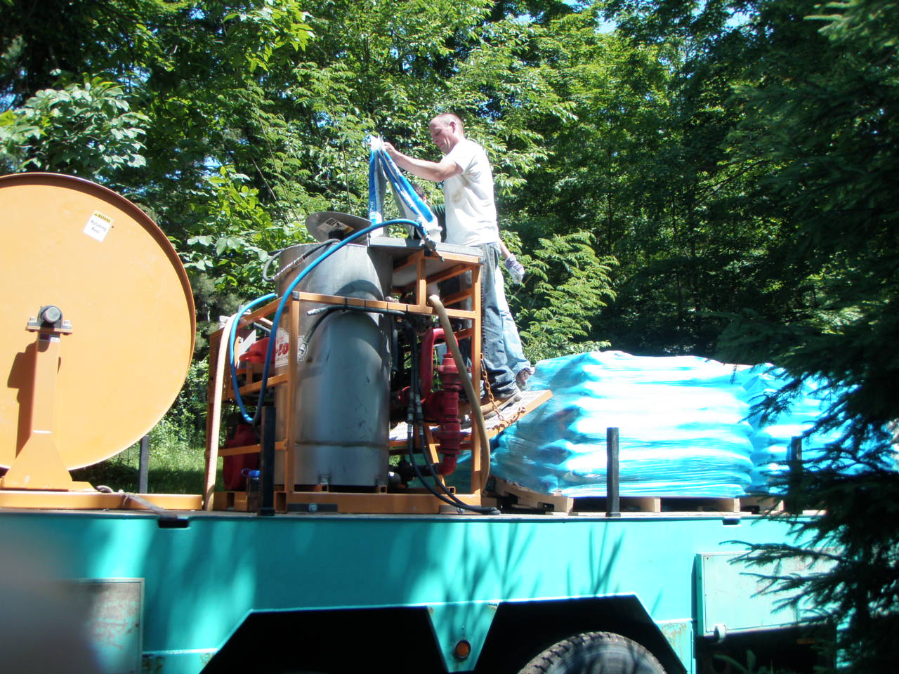
Each bag is cut open ands emptied into the mixer.

An electric motor winds the spool to raise the end of the tremie pipe as the grout is added.
At first the clean water in the hole is expelled.
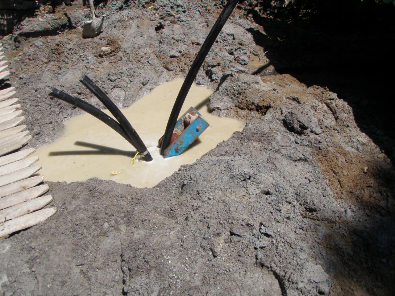
Then the grout colored water flows out, as the entire borehole is filled solid with only the two 1 1/4" loop pipes, and the grout.
Here is a video on another project where Peter Tavino is the Installer/Engineer, showing the grout and tremie pipe as it tops off.
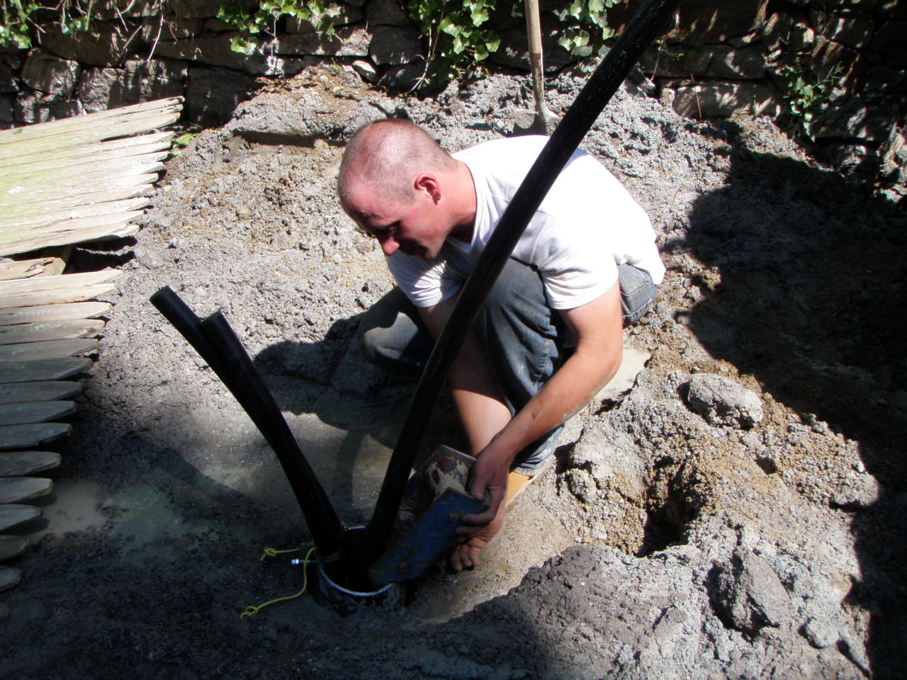
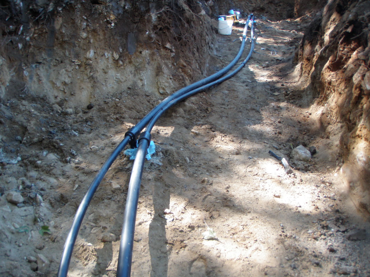
On this different job, an excavator dug a 5' deep trench to the building and the steel casing was be cut off 5' below the surface.
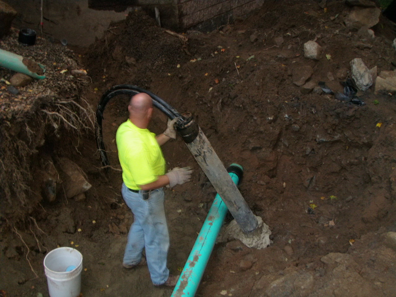
5' be;low the surface, in the trench, the bentonite grout has the consistency of peanut butter or caulk, not dried mortar.
Tees and 90 degree elbow bends are heat fused onto each loop pipe end to run a horizontal HDPE into the building.
A typical Reverse Return with 1 1 /4" and 2" trench manifold connecting the boreholes to the building.
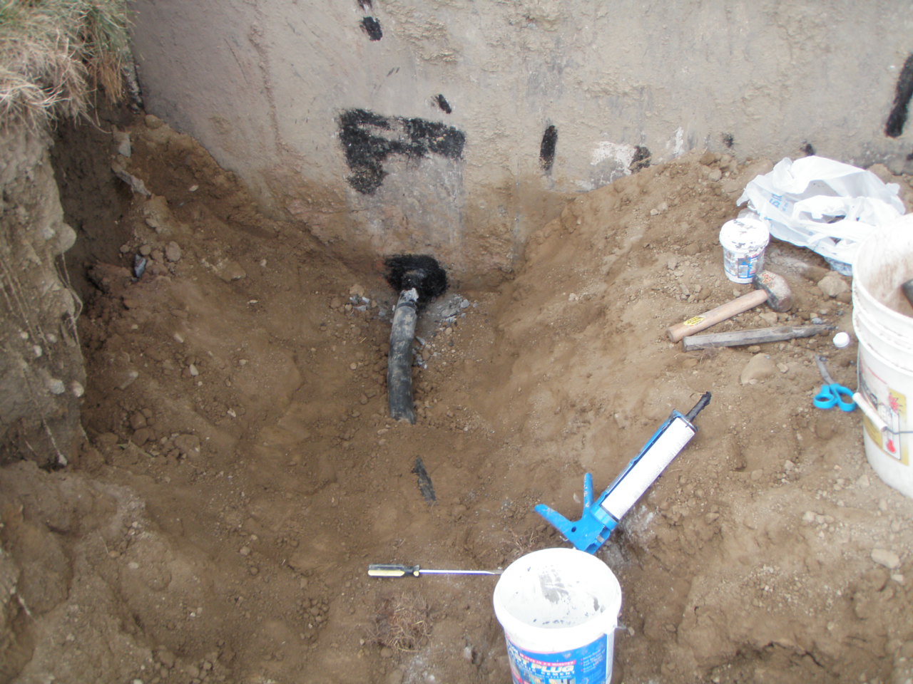
Link seals are used on the inside of the foundation wall, and hydraulic cement and tar on the outside.
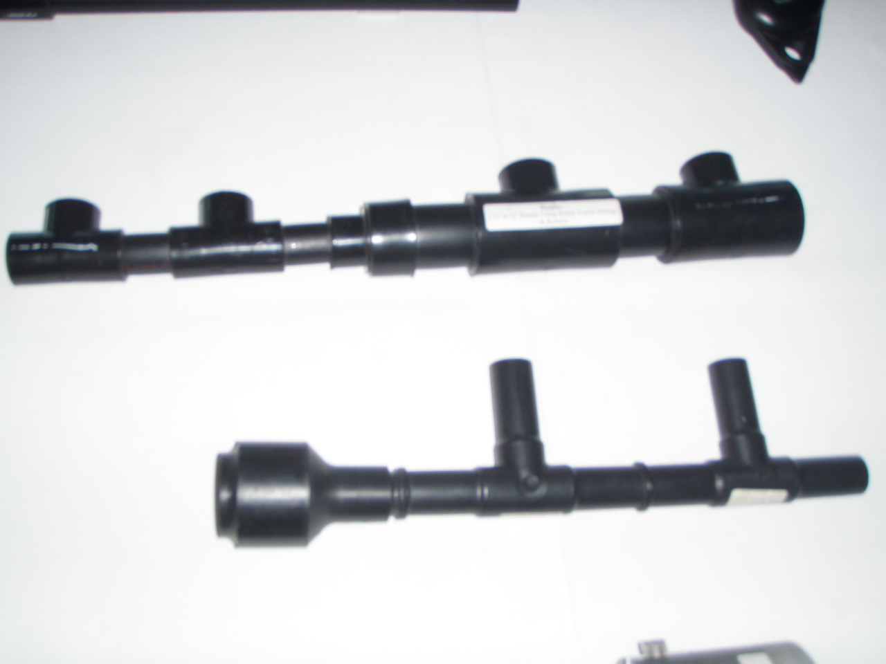
Alternately, for more bore holes, connect the circuit loops with staggered size manifolds as shown above.
Any buried connection of HDPE loop pipe is by socket or butt heat fusion with a device like this one above.
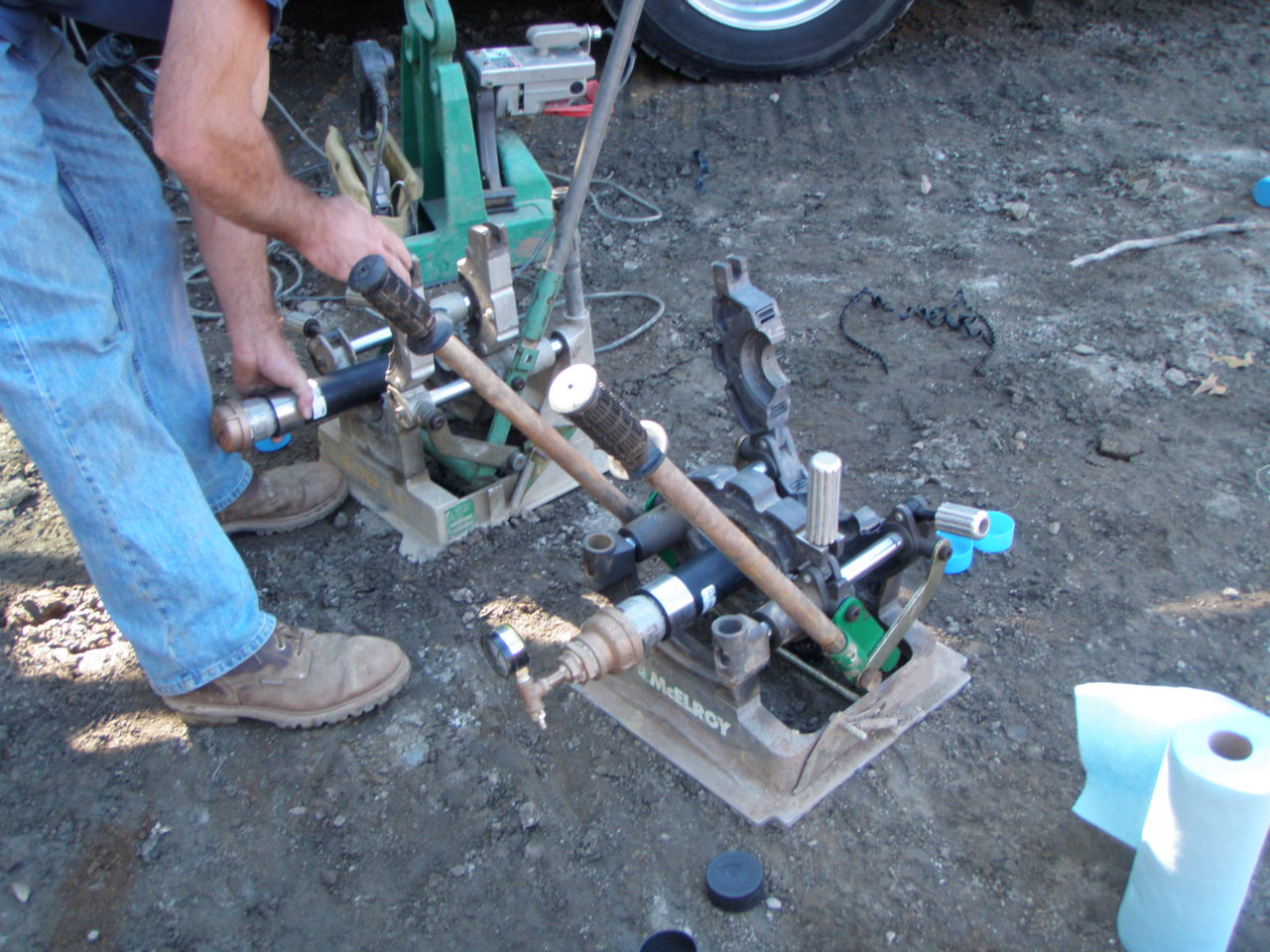
This closed loop will be filled with water and food based propylene glycol, just like in a horizontal trench loop.
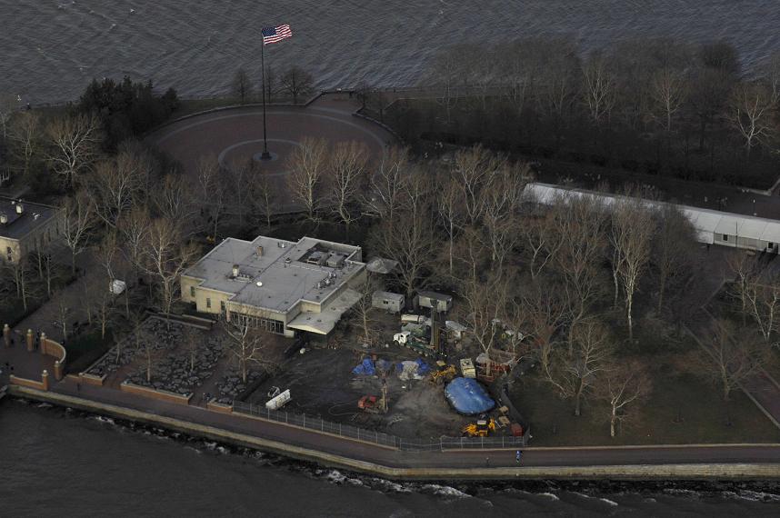
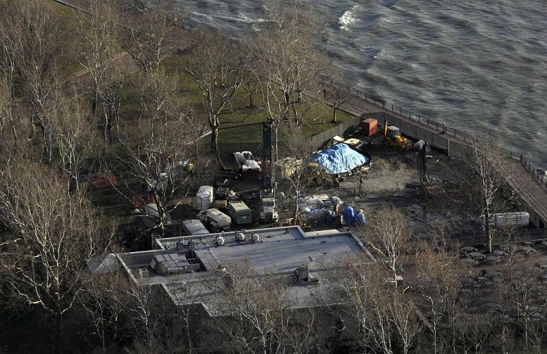
Another local well drilling company that focuses on large scale projects is CT Wells in Bethlehem.
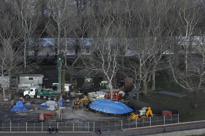
Here are pictures of the geothermal wells they installed for energy use at the service building of the Statue of Liberty.

Tower up!

Thank you Anthony for sending me this thermal conductivity project file for one of your drilling projects:
College students and Installer Candidates will be very interested in it.
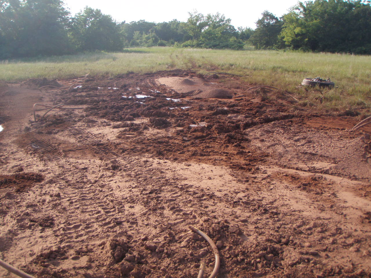
And down south in predominantly cooling mode, loops reject heat into the red brown clay loam:
Completed holes will be connected by an excavated trench.
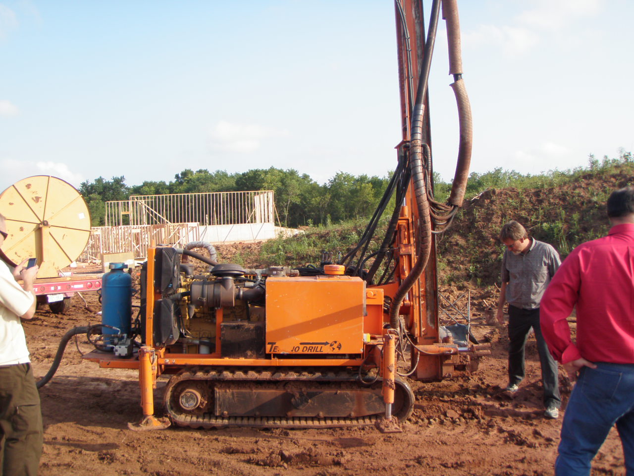
Techno Drill on tracks.
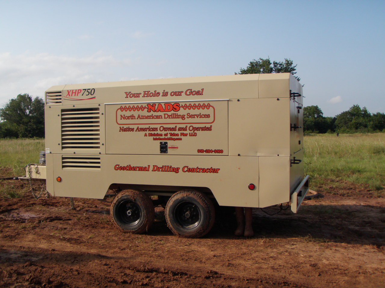
Grout rig with hopper and tremie reel.
Here was the Sample Calculation Peter Tavino presented to IGSHPA
at their headquarters as part of his Trainer exam.
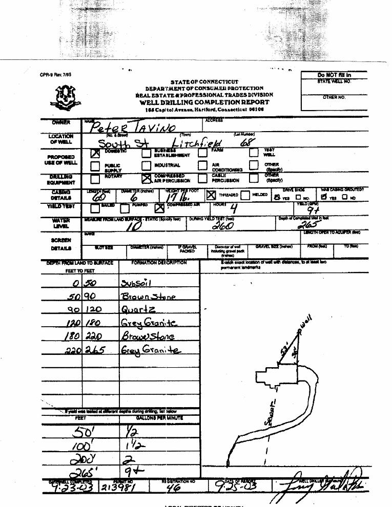
First the actual well log by Larry Grela for South Street:
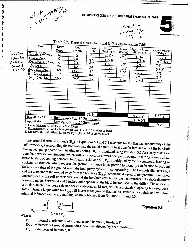
Here is the worksheet to determine the average Thermal Conductivity of this rock formation, which is
typical of the center of Litchfield.
And the Power Point Presentation of the Results
| Layer | Start Depth | End Depth | Thickness |
K BTU Hr Ft. F |
Th. x K |
|
Hardpan
|
5 |
50 |
45 |
1.44 |
64.8 |
|
Brown (Sand) Stone |
50 |
90 |
40 |
1.6 |
64 |
|
Quartz |
90 |
120 |
30 |
1.73 |
51.9 |
|
Grey Granite |
120 |
180 |
60 |
1.7 |
102 |
|
Brown (Sand) Stone |
180 |
220 |
40 |
1.6 |
64 |
|
Grey Granite |
220 |
265 |
45 |
1.7 |
76.5 |
| Sum | 265 | 425.8 | |||
|
K = |
425.8 / 265 |
|
= 1.607 |
|
|
Conclusion: Grout at 1.0 and bore hole at 1.6 would have been efficient.
But the horizontal loop, which was installed in the hardpan instead, has worked just as well.
If your project can only fit boreholes due to lack of feasible deep soils resources,
please check with us to be sure you meet all required separation distances from
water supply wells, septic systems and other facilities.
Back to Litchfield Geothermal index page